Asynchronous up down counter circuit diagram Mod-10 ripple counter Asynchronous counter: definition, working, truth table & design
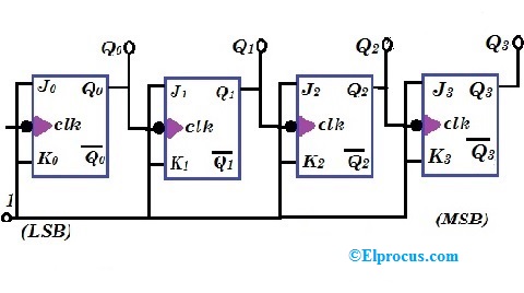
1: A 4 bit ripple counter circuit. The output of one flip-flop clocks
F-alpha.net: experiment 5
Design bcd mod 10 ripple counter using jk flip flop sequential images
Digital countersDesign a mod-5 synchronous counter using d flip flop 1: a 4 bit ripple counter circuit. the output of one flip-flop clocksAsynchronous counters synchronous logic contador contadores waveform circuito digitais bits flops assíncrono binário counting exemplo electricalelibrary counts electrical.
Mod 5 asynchronous counter circuit diagramAsynchronous up down counter circuit diagram Mod 10 ripple counter4 bit ripple counter circuit diagram.
State diagram of 3 bit synchronous counter
16. the 4 bit synchronous up counter circuit constructed with tCounter flip jk flop ripple mod using bcd logic sequential circuits [diagram] logic diagram of 4 bit ripple counterMod decade not counters while why.
Asynchronous ripple counter verilog codeCircuit diagram 4 bit binary counter Mod 10 ripple counter circuit diagramDesign bcd (mod-10) ripple counter using jk flip-flop || sequential.

Design bcd mod 10 ripple counter using jk flip flop sequential images
Why are mod-10 & mod-5 decade counters while mod-6 & mod-8 not?[diagram] logic diagram of 4 bit ripple counter Counter asynchronous circuit electronics count flip using clock digital flops state bits board tutorialSolved: 6. draw a logic diagram of a mod-8 ripple counter using three.
10+ program counter diagramCounter ripple multisim Mod 12 counter circuit diagramDigital up down counter circuit diagram.

Mod 5 asynchronous counter circuit diagram
Jk bcd ripple flops diagram verify circuit precautions4bit ripple counter diagram .
.