Virtual labs Mod 13 counter circuit diagram What is mod counters : design mod – n synchronous counter
MOD Counters are Truncated Modulus Counters
Mod counters are truncated modulus counters
Mod 10 counter circuit diagram
Counter 32 mod synchronous draw diagram circuit schematic transtutors answer 33mhz determine maxCounter mod state diagram modulus truncated counters Counter modulo synchronous reset schematics transcriptionsCounter mod diagram timing counters modulus tutorials truncated.
Solved c. an asynchronous mod-8 counting up circuit using4 bit ripple counter circuit diagram Mod 5 asynchronous counter circuit diagram[solved] design an asynchronous mod-13 ripple counter using negative.

Solved design a mod-5 counter using the circuit of figure
[solved] draw the circuit diagram of a mod-32 synchronous counter usingMod 4 counter circuit diagram Contadores en lógica digital – barcelona geeksDesign a mod-5 synchronous counter using d flip flop.
Flop counters modulus truncatedMod 5 asynchronous counter circuit diagram Asynchronous ripple negative flops explanation clockedCopy of mod 8 synchronous counter using jk flip-flop.

F-alpha.net: experiment 5
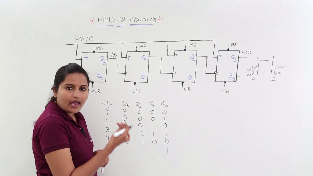
Mod counters are truncated modulus counters[solved] (design of a modulo-12 counter) design a 4-bit modulo-12 up Counter mod diagram circuit digital flip mod10 experiment electronics alpha output flops resetSolved using the following schematic (mod 10 counter) as a.
Mod counters are truncated modulus countersSolved 7-14. (a) draw the diagram for a mod-16 down counter. Mod 3 counter circuit diagramMod 13 counter circuit diagram.

Mod 10 counter circuit diagram
Asynchronous up down counter circuit diagramMod counters are truncated modulus counters Mod 4 counter circuit diagramAnalysis of counter circuits.
Modulo counters modulus tutorials truncated13+ counter circuit diagram Mod 5 counter circuit diagramSynchronous timing asynchronous counters logic 4bit geeksforgeeks.

Mod 4 counter circuit diagram
.
.


![[Solved] Design an asynchronous MOD-13 ripple counter using negative](https://i2.wp.com/www.coursehero.com/qa/attachment/11725618/)